Introduction
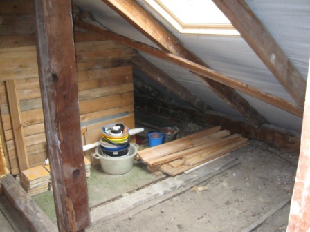
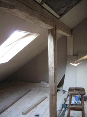
The project is to convert the remaining loft space,
adjacent to a 4th floor loft conversion apartment situated
within the roof space in a 1930,s traditional 3 floored
detached house. Although the free space to be converted is
small (approx. 6 square meters) and the roof angle
virtually cuts the total volume in half, effectively
cutting out nearly 50 percent of the floor space if to be
used by adults (head height reduced by roof slope). It
could be a practical kid’s bedroom space owing to children
needing less room height and the very low area could be
employed as a practical storage space for toys etc.
Proposed
Project (Childs Bedroom) Feasibility
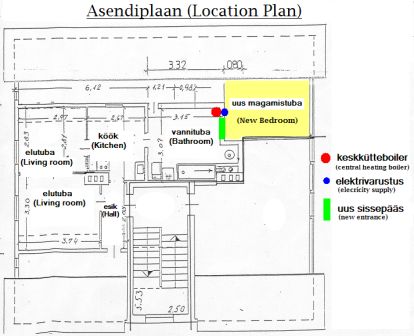
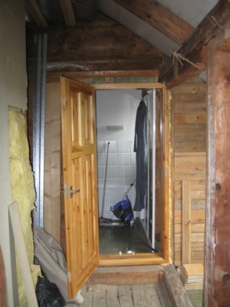
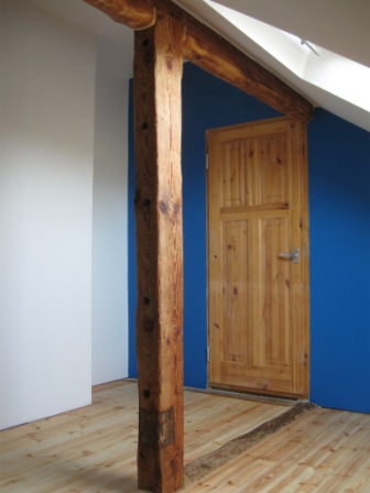
The entrance door leads from the bathroom of the
existing apartment, there is sufficient space within the
bathroom to partition a corridor from the new room to the
main living area, effectively bypassing the existing
bathroom for practical reasons. The existing central
heating system consists of a gas combination boiler which
is conveniently situated adjacent to the proposed bedroom,
simplifying the work involved with the extension to the
central heating circuit (of course, the capacity of the
existing central heating system should be quantified
before any work commences to check that it is capable of
coping with the extra radiator. Due to the new space being
a bedroom, unlike a kitchen the expected electricity load
will be minimal so a spur (electricity line) can be taken
from an existing circuit on the system. It is not
necessary to create a dedicated circuit from the main
consumer unit with its own dedicated trip switch.
Initial Inspection
The most important thing to establish is
the structural stability of the existing structure.
Because any work carried out within a previously
uninhabited structure will cause new loads, stresses &
vibration, it is vitally important to determine the
structural stability and hence, the ability of the
existing structure to cope with not only the proposed
final purpose, but also the stresses caused during the
work.
There a many factors that will effect this ability, old
structures move over time and eventually settle into
equilibrium, the stability is finely balanced, structural
beams and columns weaken with time, not just age but other
factors such as dry/wet rot, fungal and insect
infestation, degradation of metallic fixings (nails/screws
etc.). A thorough inspection must be undertaken by a
qualified professional.
I am a UK degree qualified building engineer and
from my 20 years of experience I can tell many 'horror'
stories of situations where this first 'professional
inspection' has been overlooked, leading to not just large
financial loss but also danger to life (it’s a long fall
from the second or third floor) if you don’t establish a
safe working environment to start with.
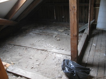
For a thorough inspection to be undertaken, it is
necessary to remove anything that covers important parts
of the structure, this includes old insulation, wallpaper,
floorboards etc. so that any hidden problems can be
confronted.
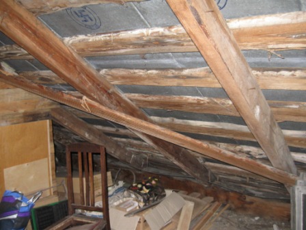
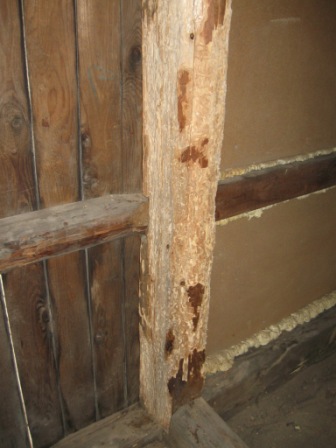
With this loft space there was very little evidence
of dry/wet rot or fungus because the structure was
waterproof and well ventilated, there was however an
infestation of wood boring beetles {woodworm)
Woodworm Treatment
Because
of the woodworm infestation, it was necessary to remove
all the existing coverings to the structural timber in
order to expose all the infected areas.
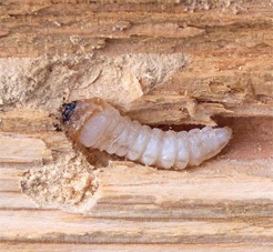
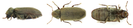
The type of woodworm was identified as the Common
Furniture Beetle (Anobium punctatum). In most cases
treatment of Common Furniture Beetle is fairly
straightforward. Any structurally-weakened timber should
be removed and replaced with pre-treated timber. All
surfaces of the affected timber should then be treated
with Woodworm Treatment applied by brush or spray.
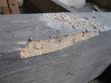
All the infected timber was cut out, first ensuring
that the remaining ‘good’ timber would be of adequate size
and strength to perform its intended structural purpose.
The depth of infection was up to 25mm in the worst areas,
leading to the requirement for one of the vertical columns
to be reinforced before the bad wood was removed and
remaining good wood then treated.
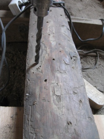
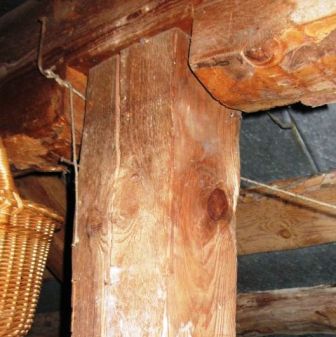
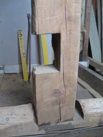
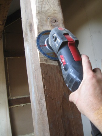
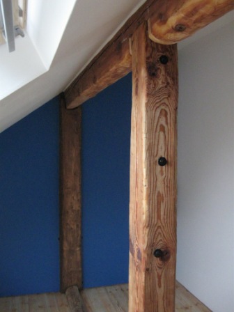
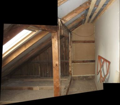
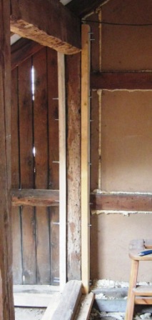
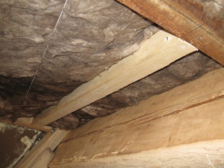
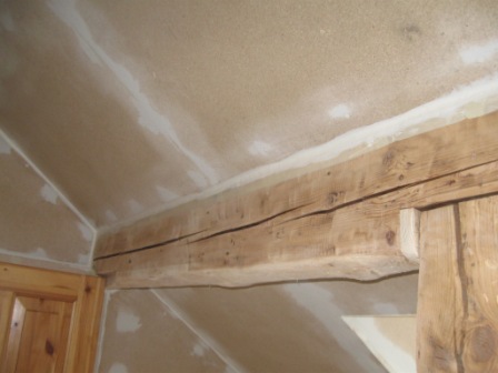
As can be seen in the following photographs,the worst
infected wood was removed gently by scraping it away, the
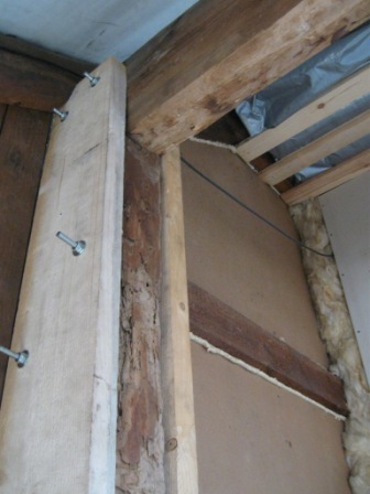
remaining good wood was then reinforced with two
(60mm by 150mm) pine columns that had been pre-treated
againt woodworm. Thes were attatched securely to either
side od the existing column, with numerous steel bolts,
penetrating completely through the ‘heart’ of the good
remaining timber, effectively joining all the timber
together to act as one structural column. This provided
adequate support to the beam resting above before the
remaining infected timber could be removed and the
remaining good timber treated.
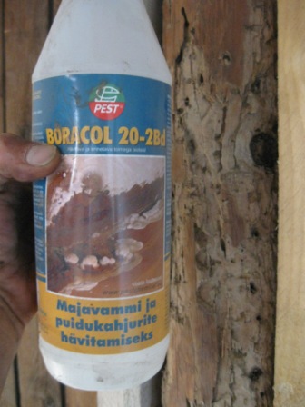
There are many solutions available for treating
woodworm but the basic application method is as follows.
Firstly however, it must be understood that these
chemicals are harmful to health and sufficient protection
must be provided against inhalation and contact with the
skin. The financial cost of this protective equipment
makes it impractical for use on a single job. It is more
economical to employ a specialist to do the job, you get
the advantage of a warranty if the treatment is
unsuccessful and also avoid risk to your health from what
is not a ‘pleasant’ job.
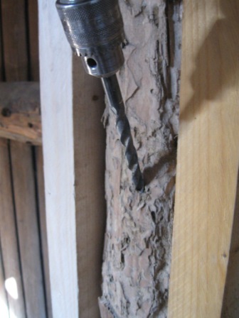
8mm diameter holes are
drilled in and around the infected areas, vertically in
beams and as close as possible to vertical in columns, to
a depth of about 40-50mm, approximately 100mm apart. The
solution was prepared according to the manufacturers
instruction and poured in the holes. The total surface
area of the infected wood was thoroughly sprayed with the
solution. The work is then stopped until the solution has
had time to do its job, according to the manufacturers
instructions.
Repair/replace
Damaged Structural Timber
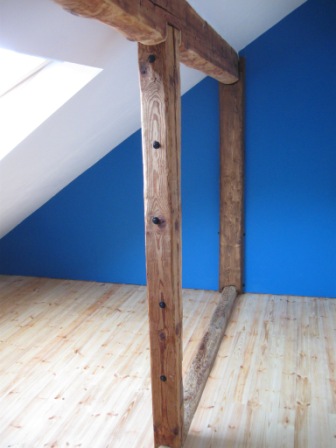
During
the life of the building, various parts of the structural
timber have become damaged or removed for various regions.
Where replacement is not possible for practical reasons,
if structural stability remains adequate, then
reinforcement is added to prevent further damage.
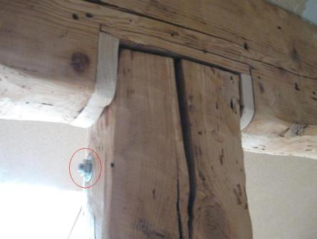
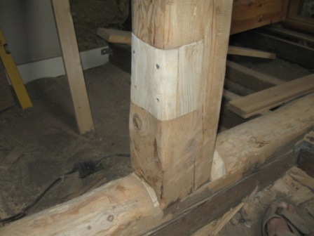
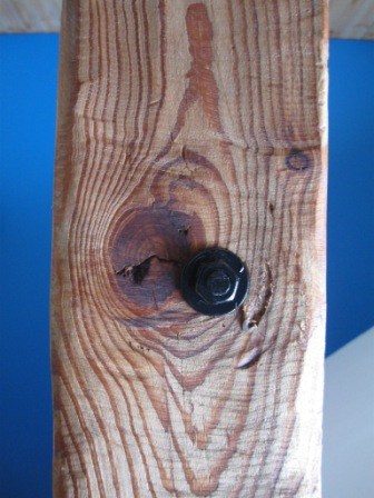
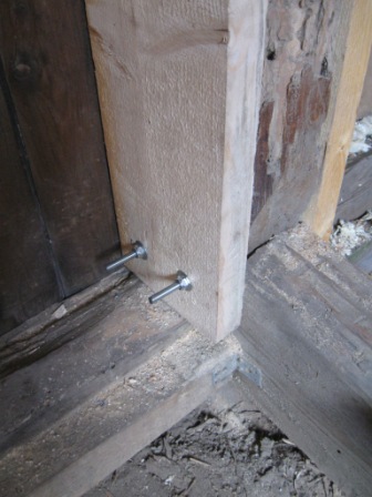
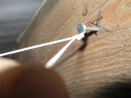
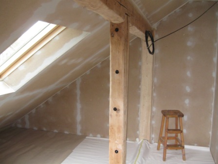
As shown in the above photographs, splits in
vertical timbers are prevented from getting worse by
clamping them together with the aid of metal bolts (ringed
in red on photograph). Other damaged areas are repaired
with fresh timber, pretreated against woodworm.
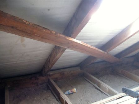
Weatherproof External Wall & Ceiling
As The entire roof covering was replaced only six months
before with metal roofing cladding and lined beneath with
moisture proof paper, there is no evidence of damp on the
underside even though there has been much rain since, so
it is safe to assume that it is weatherproof and work to
insulate the underside can proceed.
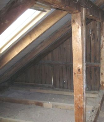
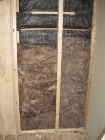
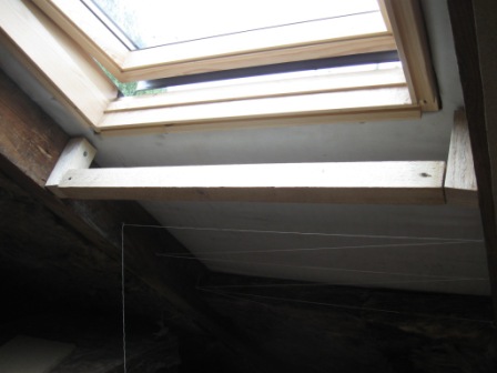
However, as can be seen from the photographs below,
daylight can be seen through gaps in the external cladding
of the external wall. This wall is exposed so its
resistance to the wind and rain needs to be improved
before the insulation can be installed.
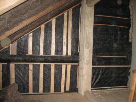
Moisture proof paper was applied to the wall, with any
joins overlapped and taped. Boards were then fixed over
the gaps in the external cladding.
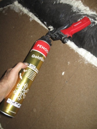
Wind resistant board was then secured over the top and any
remaining gaps were sealed with a foam filler that is
suitable to withstand freezing temperatures because it is
located on the outside of where the insulation will be
placed.
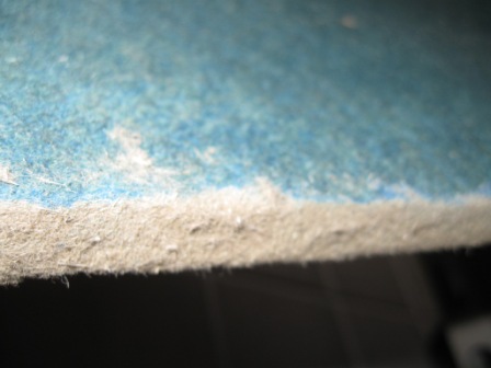
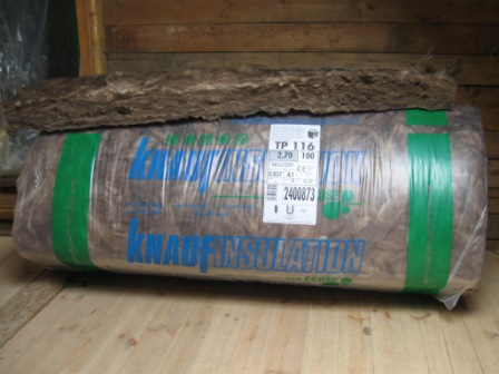
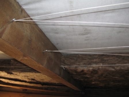
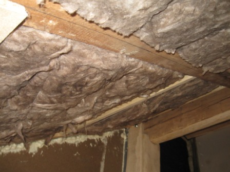
Two layers of mm thick insulation matting were then
applied to the wall, supported with a string harness so as
to prevent them from slipping out of position and leaving
gaps. The string used was synthetic so as not to rot and
break over time, letting the matting slip.
The same system was used to insulate the ceiling under the
new roof covering, creating a completely weather proof,
insulated external shell to the new bedroom. As the area
below the floor is an occupied space and heat travels
upwards, it is pointless to insulate against heat loss.
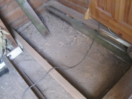
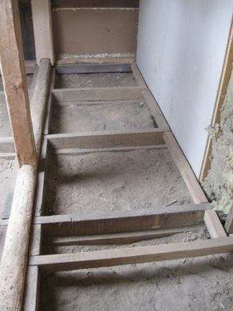
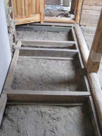
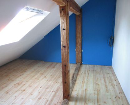
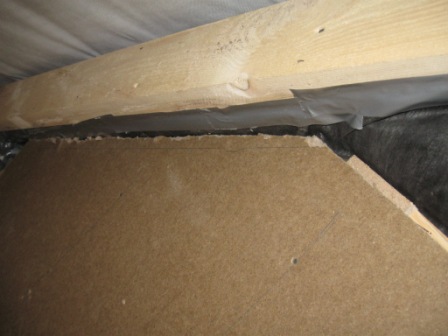
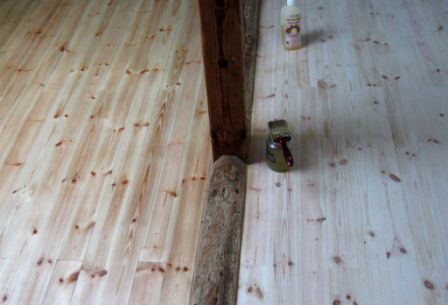
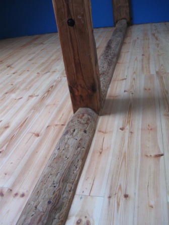
Install Floor
Support Structure
When the interior had effectively been protected against
water leaks and dramatic changes in temperature and
humidity, the new floor could be started. The
existing beams (third floor ceiling/attic floor)were found
to be of sufficient size and adequate condition to support
the proposed floor structure for the new bedroom,
consisting of pine interlocking floorboards, resting on
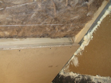
pine floor support beams. These floor support beams were
supported off the existing attic floor structure and fixed
securely as indicated in the photographs below. These
floor support beams provide two functions. They
effectively raise the finished floor level to match the
level of the floor in the existing attic accommodation, it
also provides the space under the new floor,
allowing ventilation which will reduce the chances of
problems like rotting and fungus.
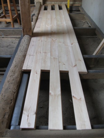
Floorboards were then selected of
adequate length and thickness to span the gaps between the
floor beams and not result in any of the board ends being
unsupported at a joint by a support beam, resulting in a
finished floor being of sufficient strength and stability
for its purpose. The boards were then laid with the joints
staggered to form a uniform pattern.
It is important to store the boards in a place of similar
humidity and temperature to where they are going to be
fitted, for some time. This is because they are usually
stored outside at the suppliers, if they are fitted
straight away, they can shrink or expand because the
moisture content will change. This will result in buckling
or gaps between the boards in the finished floor.
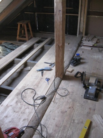
Laying The
Floor
Because the opposite walls were not parallel, as is
normally the case, it is important to start from the
center of the room and work out towards the edges, this
results in the difference being minimized when the floor
is completed. If you start from one side, the difference
will be very obvious by the time you get to the other
side. The boards are nailed through above the tongue at a
45 degree angle and punched home with a nail punch. The
boards then slot together smoothly and are hidden from
view in the finished floor. The last boards are then cut
to fit 5mm from the walls to allow for any expansion. This
gap will be hidden when the skirting boards are fitted to
the bottom of the walls.
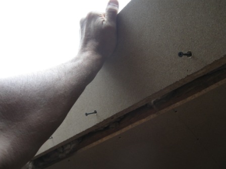
Apply Boarding
To Walls And Ceiling
6mm particle board was chosen in favor of
plasterboard because of its strength for supporting
shelves and other fittings. This was cut to the correct
size and screwed to the ceiling joists and structural
beams & columns on the walls. All edges of the boards
require fixing so additional timber was added where
required, attached to the structural supports.
A support frame for the boarding was fitted around the
‘Velux’ window, making sure that all voids were filled
with insulation wool.
The gaps where the boards join were then filled with
flexible filler and the surface of the walls and ceiling
smoothed and prepared to receive a decorative paint
finish.
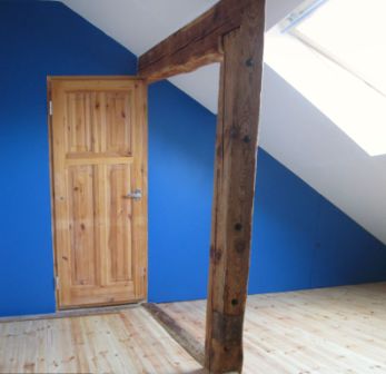
Decoration
The walls & ceiling were then painted with one
coat of base paint and two coats of top coat. The exposed
woodwork was then given a final sanding and given a finish
of linseed oil.
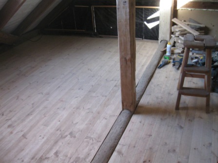
The floor, left until last was then sanded smooth, the
gaps between the floorboards and central beam were filled
with flexible parquet filler and then finished with
linseed oil.
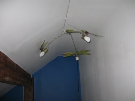
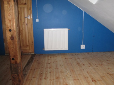
Finally, the bedroom was wired up for lighting and a
radiator fitted with pipework connected to the existing
system.